Dense stereo processing
Table of Contents
Overview
The tour of mrcal shows an example of dense stereo processing done with mrcal; details about that computation appear here.
Given a pair of calibrated (both intrinsics and extrinsics) cameras, mrcal can perform stereo processing to produce a dense stereo map. This is relatively slow, and is often overkill for what is actually needed. But sometimes it is useful, and the resulting depth images look really nice.
On a high level, mrcal stereo processing is the usual epipolar geometry technique:
- Ingest
- Two camera models, each containing the intrinsics and extrinsics (the relative pose between the two cameras)
- A pair of images captured by these two cameras
- Compute a "rectified" system: a pair of models where each corresponding row of pixels in the two cameras all represent observation rays that lie in the same epipolar plane
- Reproject the images to these rectified models to produce rectified images
- Perform "stereo matching". For each pixel in the left rectified image we try to find the corresponding pixel in the same row of the right rectified image. The difference in columns is written to a disparity image. This is the most computationally-intensive part of the process.
- Convert the disparity image to a range image using the geometry defined by the rectified system
The epipolar constraint (all pixels in the same row in both rectified images represent the same plane in space) allows for one-dimensional stereo matching, which is a massive computational win over the two-dimensional matching that would be required with another formulation.
The rectified coordinate system looks like this:

The code and documentatio refers to two angles:
- \(\theta\): the "azimuth"; the lateral angle inside the epipolar plane. Related directly to the \(x\) pixel coordinate in the rectified images
- \(\phi\): the "elevation"; the tilt of the epipolar plane. Related directly to the \(y\) pixel coordinate in the rectified images
Rectification models
A rectified system satisfies the epipolar constraint (see above). mrcal supports
two models that can have this property, selected with the rectification_model
argument to mrcal.rectified_system() or with the --rectification commandline
argument to mrcal-stereo.
LENSMODEL_PINHOLE: this is the traditional rectification model, used in most existing tools. It works decently well for small fields of view (as with a long lens), but fails with large fields of view (as with a wide lens). The issues stem from the uneven angular resolution across the image, which shoots out to \(\infty \frac{\mathrm{pixels}}{\mathrm{deg}}\) as \(\theta \rightarrow \pm 90^\circ\). This produces highly distorted rectified images, which affects stereo matching adversely, since areas of disparate resolution are being compared. This is supported by mrcal purely for compatibility with other tools; there's little reason to use this representation otherwiseLENSMODEL_LATLON: this is a "transverse equirectangular projection". It is defined with even angle spacing in both directions, so \(x - x_0 = k_x \theta\) and \(y - y_0 = k_y \phi\) where \(x\) and \(y\) are pixel coordinates in the rectified images, \(x_0\) and \(y_0\) are the centers of projection of the rectified system and \(k_x\) and \(k_y\) are the angular resolution in the two directions. This is the recommended rectification model, and is the default in mrcal
Let's demonstrate the two rectification models. In the tour of mrcal we showed a
dense stereo processing sequence. Let's re-rectify those same images and models
with LENSMODEL_PINHOLE and LENSMODEL_LATLON. This is a demo, so I ask for
the same pixels/angle resolution at the center of the image in both cases, and
demonstrate how this affects the resolution at other parts of the image.
for model (LENSMODEL_PINHOLE LENSMODEL_LATLON) {
  mrcal-stereo                     \
    --az-fov-deg 160               \
    --el-fov-deg 140               \
    --pixels-per-deg -0.05         \
    --rectification $model         \
    [01].cameramodel               \
    [01].jpg
}
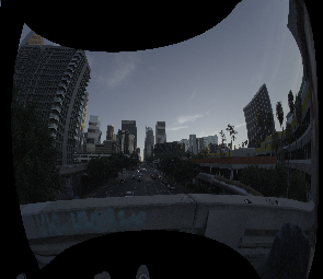
The left image rectified with LENSMODEL_LATLON (resolution at the center is
1/20 of the resolution of the original image):
The left image rectified with LENSMODEL_PINHOLE (resolution at the center is
still 1/20 of the resolution of the original image):
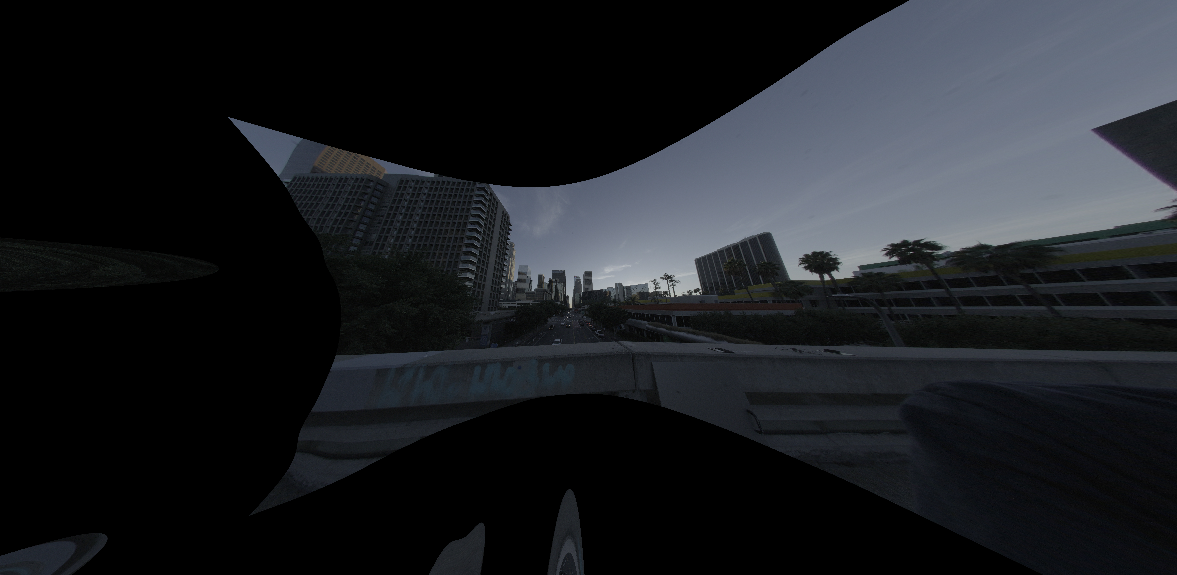
These are the actual, unscaled rectified images. Note the identical resolution
at the center of the image. And note how LENSMODEL_PINHOLE rectification
causes the image to expand dramatically as we approach the edges.
Using LENSMODEL_PINHOLE with wide lenses like this introduces an unwinnable
trade-off. If you choose the pixels/angle resolution to keep all your
information at the center, you'll get a huge image, with low-information pixels
at the edges. But if you want to reduce this expansion by lowering the
resolution, you'll lose data at the center. Or you can cut off data at the
edges. No matter what you do, you either lose information or you're stuck with a
huge image.
And even if this was all fine, with LENSMODEL_PINHOLE the stereo-matching
algorithm has to match image patches with widely different resolutions.
LENSMODEL_LATLON solves all these issues with no down sides, and is thus the
recommended rectification function.
Interfaces
Currently stereo processing is available via the mrcal-stereo tool. This tool
implements the usual stereo processing for a single frame.
More complex usages are available via the Python APIs and the C functions in
stereo.h. A sequence of images captured with a stereo pair can be processed
like this:
mrcal.rectified_system()to construct the rectified system defined by the stereo pairmrcal.rectification_maps()to construct the pixel mappings needed to transform captured images into rectified images. This is relatively slow, but it depends on the relative stereo geometry only, so this can be computed once, and applied to all the subsequent images captured by the stereo pair- For each pair of captured images
mrcal.transform_image()to generate rectified images- stereo matching to compute disparities. mrcal does not provide its own
method, and the
mrcal-stereotool uses the OpenCV SGBM stereo matcher. Any stereo matcher can be used. The result is a disparity image, where each pixel in the first rectified image is mapped to a corresponding pixel offset from the same feature in the second rectified image mrcal.stereo_range()to convert the disparities to ranges, which can then be used to produce a point cloud
A demo of the process if shown in the tour of mrcal.